CCP and timer1 questions
Moderators: David Barker, Jerry Messina
CCP and timer1 questions
I would like to use timer1 and ccp1 to calculate the frequency of an RPM signal. I am using an 18F4550 chip, with the internal oscillator set at 8MHz. I have a very vague understanding of how the ccp and timer1 work, but am confused on how to actually use them to implement what I intend to do. I have a clean signal from my ignition coil, and using a multimeter I can see ~35 Hz at idle (car idles at ~1000 RPM, 2 pulses per revolution, so 35*30 = RPM). What I would like to do, is use timer1 to count for a given interval, say 100ms, while counting pulses with the ccp module during this interval. That would allow me to calculate my RPM from this value (10*ccp value*30 = RPM) if I am doing the math on that correctly. So, with my vague understanding of this, all I really know that I need to do is start the timer and give it a specific interval, have it interrupt the ccp counter, reset the timer, do my calculation on the ccp value, and reset the ccp counter variable. What I do not understand, is how exactly to implement all of this in the code. (The calculations, oscillator config, and other general info I know how to code, just not the timer1, ccp, and interrupt parts) Any advice would be greatly appreciated, and sorry for the lengthy post.

I recently made a frequency measuring device using a 18F2410. I used the internal clock at 8MHz and it was able to reliably measure frequencies from 0 to 9kHz. Although I didn't use CCP at all. Instead I used Timer0 to count the pulses and the ISRTimer module to periodically check Timer0 and calculate the corresponding frequency.
You can read all about the ISRTimer module in the help files but I'll give you a few hints on using Timer0 as a pulse counter. It can be a little tricky since you have to deal with reading registers that are changing continuously.
First to initialize Timer0 for counting
Now for a function that returns the count.
You can read all about the ISRTimer module in the help files but I'll give you a few hints on using Timer0 as a pulse counter. It can be a little tricky since you have to deal with reading registers that are changing continuously.
First to initialize Timer0 for counting
Code: Select all
T0CON.7 = 0    'stop timer0 if its running
T0CON.4 = 0    'increment on rising edge
T0CON.5 = 1    'Put Timer0 in counter mode
T0CON.6 = 0    '16 bit mode
T0CON.3 = 1    'no prescaler

TMR0H = 0       'clear the high byte of the count register
TMR0L = 0       'clear the low byte of the count register

T0CON.7 = 1 'start timerCode: Select all
Function GetCount(PulseCount as Word)

   PulseCount.Byte1 = TMR0H   'get high byte first
   PulseCount.Byte0 = TMR0L   'get low byte next
   TMR0H = 0   'clear high byte
   TMR0L = 0   'clear low byte

End FunctionThere are several different methods depending on the resolution you need. You hit on one of the simpler methods. Count the number of pulses for 1 second and multiply by 30 (using 2 pulses per rev).
If you had sensors that produced 60 pulses per revolution, you just count the pulses during a 1 second period and that's your RPM.
You can do the same by mathematical extension. Your counts are 30:1 for a 1 second duration to get RPM, or, 30 x pulses for 1 sec equals RPM. 33 pulses would mean 999 RPM. 333 pulses would mean ~10000 RPM. 2184 pulses/sec would translate to 65520 RPM.
Feasibly you can have an RPM meter with a range of 30 to 65520 RPM with a 30 RPM step resolution.
I can recommend using Timer0 (T0CK1 input) as a simple counter. Then setup CCP or another timer with interrupts to create a 1 second period. If your RPM is not expected to exceed 7650 RPM, Timer0 counter only has to be 8-bit, else it should be 16-bit.
1 second is a good refresh period. It makes for a stable display... not too much bouncing of the numbers for variations in engine RPM.
I won't go into it here but you can extend this method to the 2nd or 3rd second (grabbing an update for the display at each point) and increase the resolution to 15 and 10 RPM.
The best accuracy that can be obtained quickly is by using the CCP Capture method. This autoloads the Timer1 count into the CCPR1L/H registers between pulse triggers on the CCP1 input pin. In your case, setup Timer1 with a prescale of 2, which produces a 1us tick @ 8MHz, and can still result in a broad range of accurate RPM readings from 458 to 60000+.
The formula being 30,000,000us / CCPR1 = RPM. A CCPR1 value of 30,000 (30000us) will show 1000 RPM. A CCPR1 value 29910 (29910us) will show 1003 RPM.... and so on.

Hi XOR !
I know this thread is a bit old, but I have a doubt about it :
I´m trying to read the on-time of one of my car´s injectors.
What I would like to know is : for how long the injector was "ON" during a period of time. let´s say ... 500 ms
Is it possible to do that using CCP1 ?
I have already the time-base of 500ms on TMR2.
Thanks
Sérgio
Hi Guys,
well, after some testes, I´m still stuck on how to implement the On-time reading in SwordFish.
I found a document on Microchip Site called "CCP and ECCP Tips´n Tricks", where they give some advices on how to work with de CCP.
I read the material and found the following :
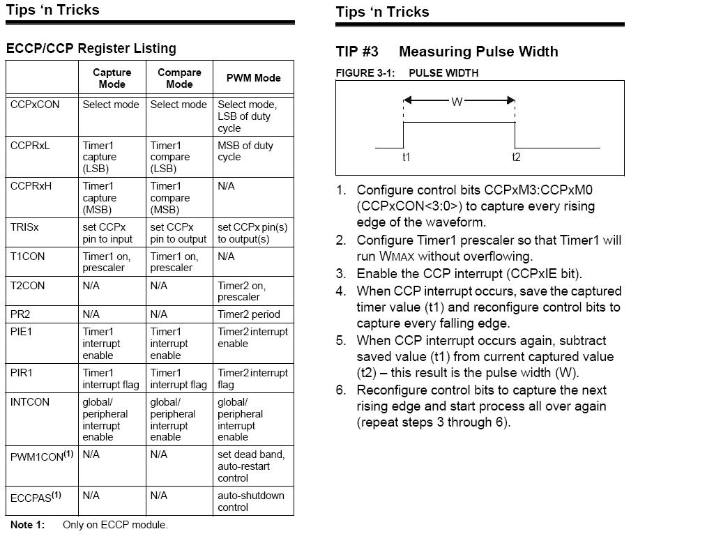
I´m using the following example from the forum to do my testes :
Now... after many many readings and testes, I have to admit : I DON´t know how to configure the TIMER1 to measure the the elapsed timer.
So, please, could some one help me to configure it ?
Thank you very much !
Sérgio
well, after some testes, I´m still stuck on how to implement the On-time reading in SwordFish.
I found a document on Microchip Site called "CCP and ECCP Tips´n Tricks", where they give some advices on how to work with de CCP.
I read the material and found the following :
I´m using the following example from the forum to do my testes :
Code: Select all
// device and osc...
Device = 18F452
Clock = 10

// import modules...
Include "ISROnChange.bas"
Include "Utils.bas"

Sub ElapsedTimer()

End Sub

// event handler...
Event OnChange()
    while PORTB.7 = 1
      ElapsedTime()
    End
End Event

// program start...
SetAllDigital
SetRBMask($80)                      // only interested in PORTB.7 on change events
ISROnChange.Initialize(OnChange)    // initialize the OnChange module, pass OnChange event handler

// loop forever...
While true
High(PORTD.1)
DelayMS(50)
Low(PORTD.1)
DelayMS(50)
WendSo, please, could some one help me to configure it ?
Thank you very much !
Sérgio