Coding and general discussion relating to the compiler
Moderators: David Barker, Jerry Messina
-
Jon Chandler
- Registered User

- Posts: 185
- Joined: Mon Mar 10, 2008 8:20 am
- Location: Seattle, WA USA
-
Contact:
Post
by Jon Chandler » Sun Jan 08, 2023 7:16 pm
Wow. The TM1638 is much simpler to use! I'm not planning on reading the switches (at this point), so the clock is just push-pull for now. So the standard shift module works fine w/o any changes.
The TM1638 data sheet takes some careful reading, but I configured the shift module, sent commands and my first run of the program worked as expected. All segments illuminated except digit 2 just to be sure it's really doing what I want.
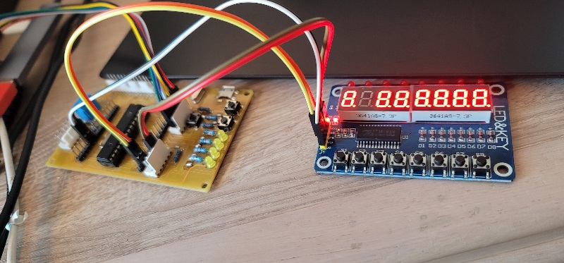
- First test run
- 20230108_105909.jpg (126.46 KiB) Viewed 3075 times
-
Jerry Messina
- Swordfish Developer
- Posts: 1473
- Joined: Fri Jan 30, 2009 6:27 pm
- Location: US
Post
by Jerry Messina » Mon Jan 09, 2023 12:41 pm
If you use the Shift module then both the clk and data pins will be actively driven high and low, so you could end up with contention issue on the data line during the ACK phase (9th clock) when the TM1637/TM1638 is pulling the data low.
-
Jon Chandler
- Registered User
- Posts: 185
- Joined: Mon Mar 10, 2008 8:20 am
- Location: Seattle, WA USA
-
Contact:
Post
by Jon Chandler » Mon Jan 09, 2023 1:34 pm
The TM1638 interface is completely different. No ack like the TM1637.
The TM1638 only drives the DIO line when scanning keys. If you don't request a key read, it will never try to drive DIO.
The TM1638 uses a 3 wire interface – clock, DIO and STB, which is more like /CS than a strobe.
-
Jerry Messina
- Swordfish Developer
- Posts: 1473
- Joined: Fri Jan 30, 2009 6:27 pm
- Location: US
Post
by Jerry Messina » Mon Jan 09, 2023 4:03 pm
My bad. I thought the 1638 was I2C... don't know where I got that idea
-
Jon Chandler
- Registered User
- Posts: 185
- Joined: Mon Mar 10, 2008 8:20 am
- Location: Seattle, WA USA
-
Contact:
Post
by Jon Chandler » Mon Jan 09, 2023 4:37 pm
I did say that earlier, based on comments posted around the TM1637. Seems to be a lot of confusing information around about these guys.
The TM1638 datasheet is much improved over the TM1637 datasheet, and includes a detailed timing plot with minimum intervals shown. There are still a few parts that require some thought to make sense.
I'll post details about making it work over the next few days.
-
Jon Chandler
- Registered User
- Posts: 185
- Joined: Mon Mar 10, 2008 8:20 am
- Location: Seattle, WA USA
-
Contact:
Post
by Jon Chandler » Tue Jan 17, 2023 9:07 pm
Man this has been a slog! After getting the TM1638 board bent to my will, I added "the easy part" - a DS3231 clock module. I've used these before with good results, using the DS1307 RTC module available here. with some slight modifications. Easy, except for the fact that it didn't work. I'll spare you the details of checking that SDA and SCL were connected to the right pins, searching for some enable bit I had missed, etc., etc.
One of the two-pin Dupont jumpers was faulty! Argh. I found the problem with a simple test. Since the pullup resistors are on the DS3231 module rather than my micro board, a short program to print of the state of the SDA and SCL pins with the module attached but without any other setup told the story. PortC.3 = high. PortC.4 = low. What????
I don't know if the defective cable may have been part of the problem with making the TM1637 display work.....
-
Jerry Messina
- Swordfish Developer
- Posts: 1473
- Joined: Fri Jan 30, 2009 6:27 pm
- Location: US
Post
by Jerry Messina » Fri Jan 27, 2023 4:08 pm
Jon was nice enough to send me some TM1637 and TM1638 modules to play with (thanks, Jon).
Initially, the TM1637 module caused me some grief. It's a DILTAO TM1637 4-digit clock module (Amazon ASIN B0B73MBP8V),
but the same board is available from a number of different chinese vendors. It doesn't come with any schematics I could find,
but it seemed to be similar to the example circuit shown in the TM1637 datasheet.
The example circuit has 10K pullups + 100pF to GND on the CLK and DIO lines to be used in an open-drain configuration like I2C.
That would give a risetime of about 1us on the low to high signal transitions.
Tried my driver code and no go. Finally broke out my scope, and to my surprise the signals had a risetime of ~100us!
That would explain why some of the arduino code had the bit timing set for 100us. That would mean the caps aren't 100pF,
but more like 0.01uF... I think they just used that same value for all the caps on the pcb.
Anyway, once I slowed it down things came to life. As a sanity check I removed the two caps on the CLK and DIO lines and the module worked with times below 1us, which is about what the TM1637 datasheet shows.
Attached is the updated driver code and a sample app for the K22.
On to the TM1638...
-
Attachments
-
- TM1637_v1.2.zip
- (5.22 KiB) Downloaded 85 times
-
Jon Chandler
- Registered User
- Posts: 185
- Joined: Mon Mar 10, 2008 8:20 am
- Location: Seattle, WA USA
-
Contact:
Post
by Jon Chandler » Sat Jan 28, 2023 7:13 am
Thanks Jerry for taking a look at the TM1637 board and getting it to work. I'm glad you solved the mystery to get it working! I've been working on this on a cruise ship without any gear besides a PICkit 2 and was feeling kind of stupid when several different approaches didn't work.
I have the TM1638 module working nicely. The TM1638 uses a little more conventional shift-register approach, and probably more importantly, the dev board I have (and the kind I sent you) don't have the filter caps the schemmatic recommends.
The TM1637 and TM1638 cost about 20 cents and 25 cents respectively, and the modules with 7-segment LED digits are only a few bucks a piece.
I've designed a board using the TM1638 and a DS3231 RTC clock chip to make a high-accuracy battery-backed clock. If the power goes off, the correct time will be displayed when power is restored. Four digits display hour and minnutes, the other digits, in groups of two, can display temperature (thanks to the DS3231), the month, the date or seconds. The TM1638 provides for 10 segments per digit which may be used for individual LEDs. My intent is to indicate the day of the week with 7 LEDs, with the 8th in indicate am/pm. These boards are ready to go to JLC as soon as I have a solid internet connection.
In this case, I did the code development using dev modules before laying out the pcb, just to be sure that a 25 cent LED display driver was up to the task.